A linear gear is a mechanical transmission component used to convert rotary motor movement into controlled linear motion. In industrial automation, linear gear systems are commonly associated with gear rack mechanisms, where a rotating pinion engages with a linear rack to move a carriage or machine component along a straight path.
Compared with screw-based linear transmission, a gear rack and pinion system can be particularly useful for long-stroke movement, high-load applications, and large automation equipment.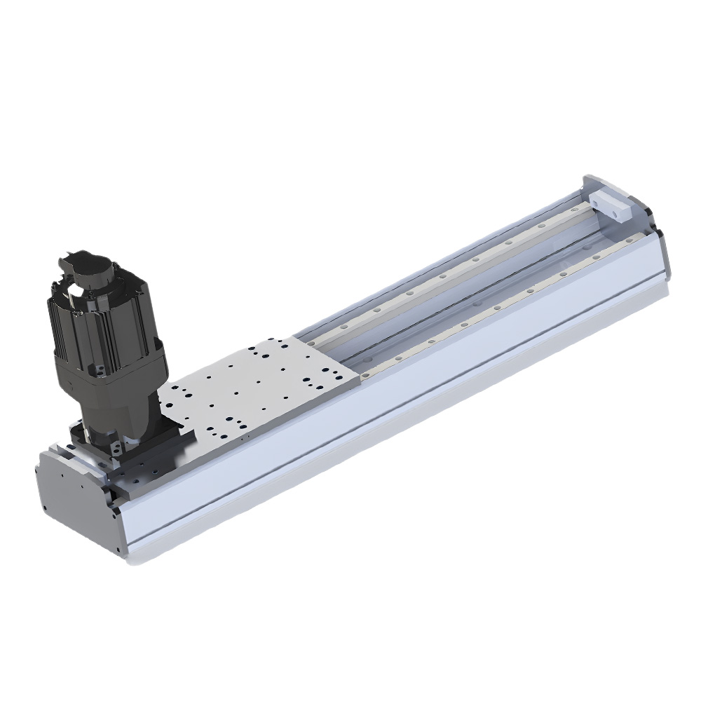
For OEM equipment manufacturers, the required gear, rack, stroke, load, speed, mounting structure, and motor configuration can vary significantly. A custom linear gear system allows these parameters to be designed around the actual machine requirements.
A linear gear is generally used to transmit rotary motion into linear movement through a gear-and-rack mechanism.
A typical system consists of:
When the pinion rotates, its teeth engage with the rack and generate linear movement along the rack.
The basic motion relationship can be represented as:
Rotary Motor → Pinion → Linear Gear Rack → Linear Movement
This configuration is particularly useful when a machine requires long travel without relying on a long ball screw or similar mechanical transmission.
One of the major advantages of a rack-and-pinion linear gear system is its ability to support long travel distances.
Unlike a conventional ball screw, where the screw length can become an important design limitation as the stroke increases, a rack can be configured in sections to create a much longer travel path.
This makes linear gear systems suitable for:
The actual maximum travel depends on the rack design, guide structure, motor system, machine stiffness, and required positioning performance.
Gear rack systems can be designed for applications involving relatively high loads.
The actual load capacity depends on factors such as:
For custom OEM applications, the rack and pinion should be selected according to the complete load and motion profile.
A properly configured gear rack system can support relatively high linear speeds.
The linear speed is related to the rotational speed of the pinion and its pitch diameter.
In simplified terms:
Linear Speed = Pinion Circumference × Rotational Speed
Actual operating speed also depends on the motor, gearbox, gear ratio, load, acceleration, and machine structure.
This makes linear gear systems suitable for applications where long travel and relatively high movement speed are required.
Rack sections can be arranged along a long linear path.
This makes gear rack transmission particularly useful when a machine needs a long travel axis without using an extremely long screw.
For example, a robotic system may require a robot to move several meters between multiple workstations.
A linear gear system can provide the mechanical drive for this type of application.
The motor and pinion can be configured with different transmission ratios according to the required speed and force.
A gearbox can be used to:
This flexibility allows the drive system to be optimized for different applications.
A linear gear system can be configured according to the machine structure.
Customization may include:
This makes rack-and-pinion linear motion suitable for custom machinery.
Different linear transmission technologies have different strengths.
| Feature | Linear Gear / Rack & Pinion | Ball Screw | Belt Drive |
|---|---|---|---|
| Long stroke | Excellent | Application dependent | Excellent |
| High speed | Good to excellent | Moderate to good | Excellent |
| High load | Excellent potential | Good | Application dependent |
| Precision positioning | Good to excellent | Excellent potential | Good |
| Long-distance robot travel | Excellent | Less suitable for very long travel | Suitable |
| Mechanical transmission | Gear/rack | Screw | Belt/pulley |
| Customization | High | High | High |
| Typical use | Long travel, heavy automation | Precision positioning | High-speed transfer |
The choice should be based on the actual application rather than simply comparing individual specifications.
For applications requiring long travel and high load, a linear gear system can be particularly attractive.
For applications prioritizing very high positioning precision, a ball screw or linear motor may be more appropriate.
For high-speed, long-stroke transfer where moderate positioning performance is sufficient, belt drive can be a practical option.
One of the important applications for linear gear transmission is the robot 7th axis.
A robot can be mounted on a linear track and moved between multiple workstations.
A rack-and-pinion drive can provide the long travel required for:
The rack length can be configured according to the robot's required working range.
Large Cartesian gantry systems often require long travel along one or more axes.
Linear gear systems can be used to drive:
For large gantry systems, the gear rack can be integrated with linear guides and a servo motor to create a complete linear motion axis.
Industrial material handling equipment may need to move heavy loads over long distances.
A linear gear system can provide the required mechanical drive for:
The gear, rack, motor, and guide should be sized according to payload and acceleration.
Large machine tools may require long linear travel.
Rack-and-pinion systems can be used where the travel distance makes conventional screw-driven systems less practical.
Applications may include:
The appropriate gear accuracy and mechanical stiffness depend on the machining requirements.
Linear gear systems can move workstations, fixtures, tooling, or products along a long production line.
For example:
Loading Station → Assembly → Inspection → Testing → Unloading
A gear rack can provide continuous linear movement between multiple stations.
For large automated machines, high load and long travel often need to be considered simultaneously.
A properly designed rack-and-pinion system can be integrated with a heavy-duty linear guide to provide stable movement.
Potential applications include:
For OEM customers, a standard rack and pinion may not fit the machine's mechanical structure.
A custom solution can be designed according to:
Payload → Stroke → Speed → Acceleration → Gear Ratio → Rack Length → Positioning → Motor → Guide → Installation
The gear rack and pinion should be considered together with the guide and motor system.
A custom linear gear system may include:
This allows the rack-and-pinion mechanism to be integrated directly into the customer's machine design.
Before selecting a linear gear system, OEM engineers should define:
For vertical axes, gravity and load-holding requirements should also be considered.
For long horizontal axes, rack alignment, guide stiffness, backlash, and mounting accuracy become especially important.
For precision applications, backlash is an important consideration in rack-and-pinion systems.
Backlash refers to the clearance between mating gear teeth. Excessive backlash can influence positioning performance, especially when the direction of movement changes.
Depending on the application, engineers may consider:
Therefore, a linear gear system for a high-precision machine should be designed as a complete motion system rather than selecting the rack independently.
A custom linear gear manufacturer can help integrate the rack-and-pinion mechanism with the complete linear motion system.
Instead of selecting the rack first, the manufacturer can evaluate:
Rack + Pinion + Motor + Gearbox + Linear Guide + Encoder + Controller + Load
This is particularly useful for OEM equipment requiring non-standard stroke, long travel, high load, special mounting dimensions, or multi-axis movement.
For custom automation, the objective is to create a linear gear system that matches the machine's actual motion requirements.