A heavy duty electric cylinder is an electromechanical linear actuator designed to generate controlled linear force and movement for applications with demanding load requirements. It typically combines an electric motor, a screw drive or another transmission mechanism, a guided moving component, and a supporting mechanical structure.
Compared with actuators designed for light-duty positioning, heavy duty electric cylinders are selected for applications that may involve higher thrust, larger payloads, longer strokes, frequent operation, or more demanding mechanical loads.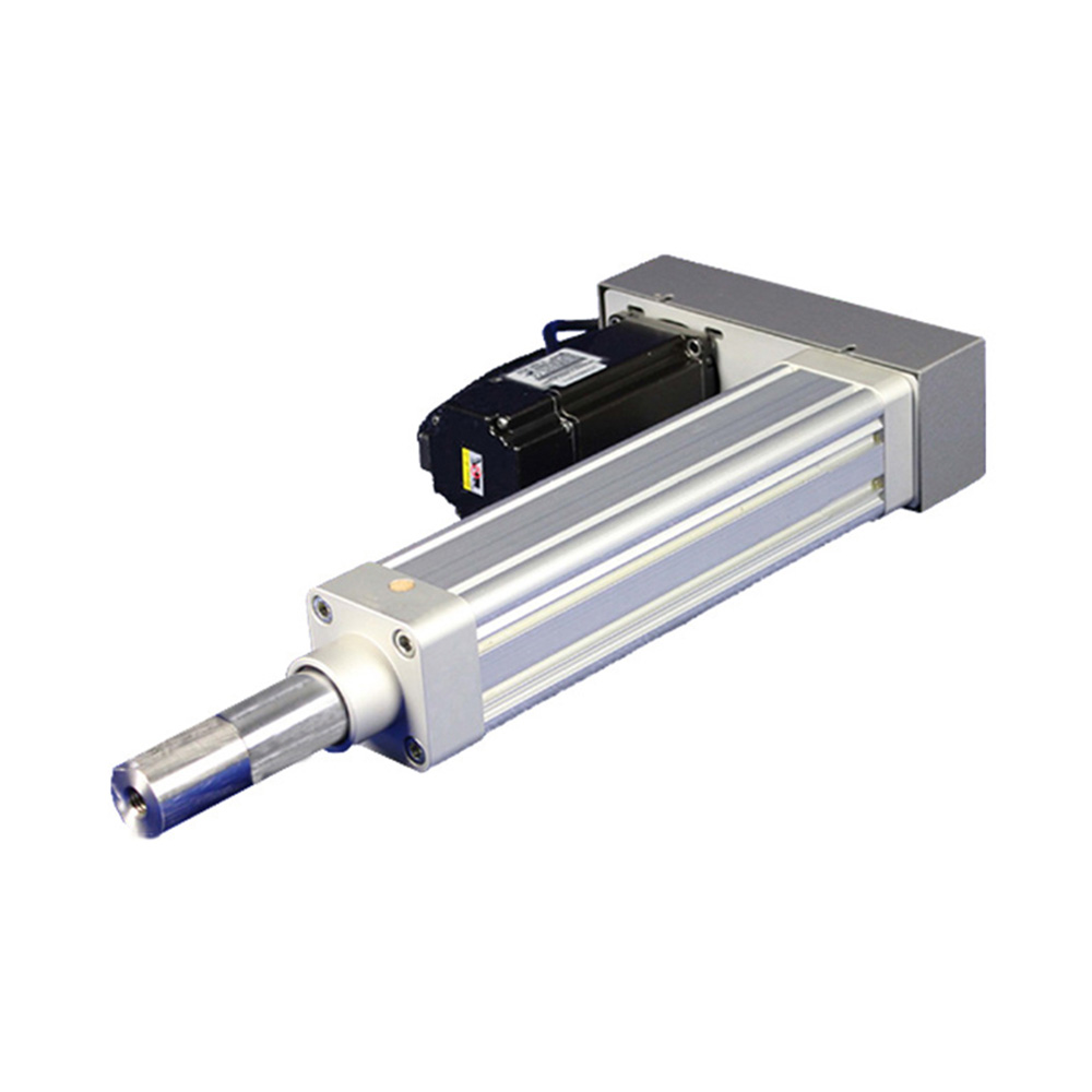
Depending on the design, a heavy duty electric cylinder may use a ball screw, lead screw, servo motor, or other compatible drive configuration. The appropriate solution depends on the required thrust, stroke, speed, duty cycle, positioning performance, and installation conditions.
For OEM equipment manufacturers and automation integrators, a custom heavy duty electric cylinder can be configured to fit specific machine dimensions, load requirements, mounting interfaces, and control systems.
One of the main reasons to choose a heavy duty electric cylinder is the need to generate substantial linear force in a controlled manner.
Depending on the mechanical design and motor configuration, these actuators can support demanding pushing, pressing, lifting, clamping, and positioning tasks.
When selecting an actuator, it is important to distinguish between peak thrust and continuous operating thrust. The required force, movement speed, stroke, and duty cycle all affect motor sizing and thermal performance.
For custom projects, manufacturers should evaluate the complete operating conditions rather than select a cylinder based only on a maximum thrust rating.
Heavy duty applications place greater demands on the actuator's screw, bearings, housing, guides, mounting interfaces, and supporting machine structure.
A suitable design should consider:
Axial load and external forces
Moving load and center of gravity
Mounting stiffness and structural deflection
Guide alignment and side-load conditions
Shock loads and acceleration forces
Expected operating hours and service life
A robust mechanical configuration helps maintain stable operation under the intended working conditions.
However, high thrust capacity does not automatically mean an actuator can withstand large side loads. Where lateral forces or bending moments are present, additional linear guides or a separate support structure may be required.
Ball screw-driven electric cylinders are commonly considered for applications requiring relatively high efficiency, controlled movement, and frequent operation.
The screw converts motor rotation into linear displacement. By selecting an appropriate screw lead, motor, and drive system, the actuator can be configured to balance thrust, speed, and positioning requirements.
A ball screw configuration may be suitable for:
Heavy-duty positioning
Automated machine loading
Pressing and clamping mechanisms
Industrial assembly equipment
Repetitive linear movement
The final selection should also account for screw life, lubrication, critical speed, buckling limits, and the load applied over the full stroke.
Heavy duty machinery often has unique space constraints and travel requirements. Standard electric cylinders may not match the required stroke or installation geometry.
Custom electric cylinders can be designed around application-specific parameters, including:
Required effective stroke and overall length
Mounting style and connection interfaces
Motor orientation and installation space
Front-end rod or load connection
Integration with linear guides or machine frames
Protective covers and environmental requirements
Custom dimensions can help OEM manufacturers integrate the actuator into existing machinery or new equipment designs with fewer mechanical modifications.
A heavy duty electric cylinder can be paired with a suitable servo or stepper motor system to control movement speed, acceleration, deceleration, and positioning.
For applications that require repeatable movement, feedback devices and compatible controllers can improve position control. If the process requires monitoring or regulating applied force, additional force sensing and control may be necessary.
Actual positioning accuracy and repeatability depend on the screw mechanism, mechanical clearances, mounting rigidity, feedback configuration, controller, and load.
For heavy loads, engineers should evaluate both positioning requirements and structural deformation under operating force.
Heavy duty electric cylinders can be integrated into automated machinery using suitable motor drives, PLCs, motion controllers, sensors, and safety devices.
Depending on the application, customization may include:
Servo motor and drive integration
Home and limit sensors
Position feedback
Programmable motion sequences
Interfaces with other linear axes
Coordination with conveyors, robots, or production equipment
For vertical lifting and other applications where a load could move unexpectedly after power loss, the design should include an appropriate braking or load-holding arrangement.
Heavy duty electric cylinders are used in industrial applications where controlled linear force and movement are required.
3.1 Industrial Lifting and Height Adjustment
Heavy duty electric cylinders can raise, lower, or adjust machine components, work platforms, and positioning assemblies. Vertical applications require careful evaluation of load capacity, mounting stiffness, braking, and protection against unintended movement.
3.2 Pressing and Forming Equipment
Electric cylinders can generate controlled linear thrust for pressing, forming, and other force-related operations. Applications requiring regulated pressing force may need a force sensor or load cell, together with a suitable closed-loop control system.
3.3 Machine Loading and Unloading
In automated production equipment, heavy duty electric cylinders can move fixtures, positioning mechanisms, and machine components during loading and unloading. Stroke length, cycle time, and external loads should be considered when selecting the actuator.
3.4 Clamping and Positioning Systems
Electric cylinders can operate heavy-duty clamping mechanisms and positioning fixtures in manufacturing equipment. Custom mounting interfaces and motion control can help coordinate the actuator with workpiece handling and processing sequences.
3.5 Heavy-Duty Material Handling
In material handling systems, electric cylinders can provide linear movement for transfer mechanisms, pushers, lifting assemblies, and load positioning devices. The design should account for the complete moving mass, acceleration, guide support, and expected duty cycle.
3.6 Custom OEM Machinery
Specialized machinery may require a combination of high thrust, non-standard stroke lengths, custom mounting dimensions, and integration with existing controls. A custom heavy duty electric cylinder can be configured around the machine's specific mechanical and operational requirements.
Electric, pneumatic, and hydraulic cylinders can all provide linear movement, but they differ in their drive systems and control characteristics.
|
Comparison |
Heavy duty electric cylinder |
Pneumatic cylinder |
Hydraulic cylinder |
|---|---|---|---|
|
Power source |
Electric motor |
Compressed air |
Pressurized hydraulic fluid |
|
Motion control |
Programmable with a suitable drive and controller |
Often suited to simpler end-to-end movement; intermediate positioning requires additional equipment |
Depends on hydraulic circuit and control system |
|
Force capability |
Depends on screw, motor, and mechanical design |
Limited by air pressure and piston area |
Can generate very high force with an appropriately sized system |
|
Positioning flexibility |
Suitable for programmable positioning |
Requires additional components for advanced positioning |
Can support controlled positioning with suitable feedback and valves |
|
Supporting equipment |
Motor drive and electrical controls |
Air compressor or air supply and valves |
Pump, reservoir, valves, and fluid lines |
|
Typical applications |
Controlled positioning, automated pressing, lifting, and OEM machinery |
Repetitive pushing, clamping, and simpler movement |
Very high-force machinery and demanding industrial applications |
A heavy duty electric cylinder can be a good choice when programmable movement, electric control integration, and reduced reliance on hydraulic infrastructure are important.
For applications involving extremely high forces, shock loads, or specialized continuous-duty requirements, hydraulic cylinders may also be worth evaluating. The best solution depends on the complete force, speed, control, safety, and cost requirements.
For OEM equipment manufacturers, a heavy duty electric cylinder should be selected according to the complete application rather than thrust capacity alone.
Custom design may be necessary when the machine has unusual dimensions, a demanding duty cycle, a specific motor interface, or a combination of load and positioning requirements.
Key customization parameters include:
Required thrust: Peak and continuous force during operation.
Stroke length: Effective travel and available installation space.
Operating speed: Target linear speed and acceleration.
Duty cycle: Frequency of movement, operating hours, and rest periods.
Screw mechanism: Ball screw or another suitable transmission arrangement.
Motor configuration: Servo motor, stepper motor, or compatible drive.
Positioning requirements: Accuracy, repeatability, and feedback needs.
Mounting arrangement: Flange, clevis, trunnion, or other suitable interfaces, depending on the design.
External loads: Side loads, bending moments, shock loads, and load eccentricity.
Operating environment: Dust, temperature, moisture, and lubrication requirements.
Safety requirements: Braking, load holding, limit protection, and emergency stop integration.
Providing these details during the engineering stage helps the manufacturer evaluate whether the proposed actuator can meet the required performance and service life.
Before requesting a quotation, consider the following steps.
Step 1: Calculate the required force. Include the load, friction, gravity for vertical movement, acceleration forces, and any external resistance.
Step 2: Confirm the stroke and installation dimensions. Specify the effective travel, mounting position, and available space for the cylinder and motor.
Step 3: Define the motion profile. Determine the target speed, acceleration, cycle time, and operating frequency.
Step 4: Evaluate the screw and motor. Confirm that the transmission mechanism and motor can support the required thrust, speed, and duty cycle.
Step 5: Check mechanical stability. Review screw buckling limits, critical speed, mounting stiffness, and the need for external guides.
Step 6: Establish control and feedback requirements. Determine whether the application requires position feedback, force monitoring, or coordinated motion.
Step 7: Assess safety and maintenance. For vertical or high-load applications, evaluate braking, load retention, lubrication, and maintenance access.
Step 8: Confirm the custom design with the manufacturer. Provide technical drawings and operating conditions so the supplier can evaluate the configuration before production.
This process reduces the risk of choosing an actuator that meets the nominal load requirement but does not suit the actual operating cycle.
A capable manufacturer should evaluate the complete application, including thrust, screw selection, motor sizing, mechanical structure, mounting arrangement, and control integration.
For OEM customers, useful supplier capabilities include:
Application-based actuator selection
Custom stroke and mounting dimensions
Motor and screw configuration options
Technical drawings and mechanical interface support
Evaluation of duty cycle and load conditions
Integration support for industrial automation systems
KNK Technology provides linear motion products and customized solutions for industrial automation. Customers developing high-load positioning or linear actuation equipment can explore the KNK Technology and discuss their project requirements with the engineering team.
When requesting a custom solution, include the required thrust, stroke, speed, duty cycle, mounting dimensions, and operating environment. These details help establish a suitable technical starting point.