

T Series Elliptical Conveyor System
0.05mm repeat positioning accuracy with 1000mm/s speed. The T Series integrates high-strength, modular design for reliable, cost-effective precision conveyor systems.
View productSpecifying a custom linear module moves faster when the request already answers the questions engineers usually have to chase. This guide explains what drawing-based customization can change, how the published load, speed and accuracy figures translate into real capability, and which details help you compare one linear module manufacturer with another before a build is confirmed.
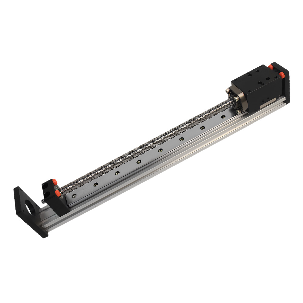
Customization is not a single upgrade — it is a set of levers. Each lever changes the drawing, the price and the lead time, so the request should say which ones are fixed and which ones can move.
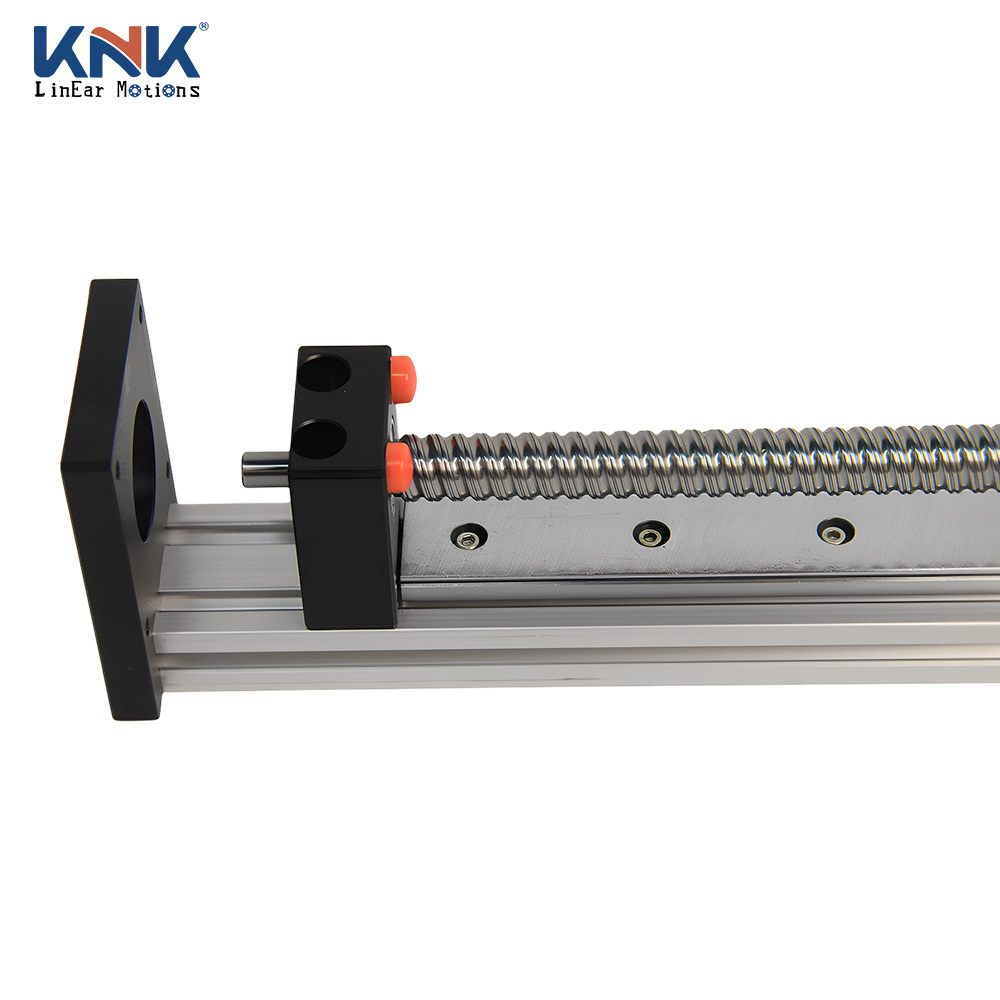
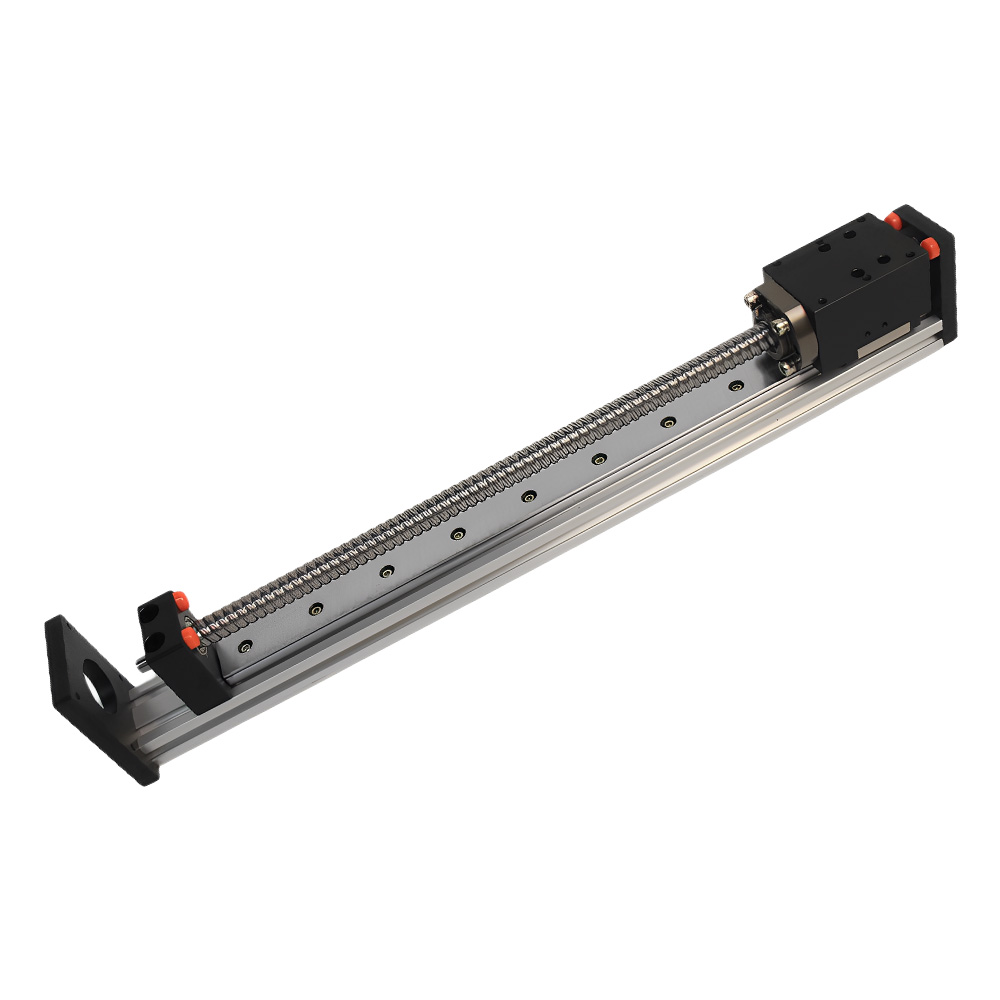
The MR40G is published as a ballscrew series module with an embedded closed high-precision ball screw actuator. If your application needs a different drive principle, say so at the first contact — it changes which platform the drawing starts from.
No stroke figure is published for the MR40G, so travel length is a request input, not a catalogue value. State the working stroke plus the extra travel you need for setup and overtravel.
Horizontal, vertical, inverted or gantry-mounted all change bearing load and fixing points. A sketch of the orientation is often faster than a paragraph of description.
Servo or stepper, coupling position, brake requirements and the drive you already standardize on should be stated, so the interface is drawn once instead of reworked later.
Give the accuracy you need at the tool, not only at the module, and include gripper and workpiece mass in the load figure. The published 150 kg and 0.01 mm values are the platform's ceiling and positioning figures.
The MR40G's closed ballscrew design limits external contamination and reduces maintenance. Cells with chips, dust or coolant should describe the exposure so the sealing level can be confirmed on the drawing.
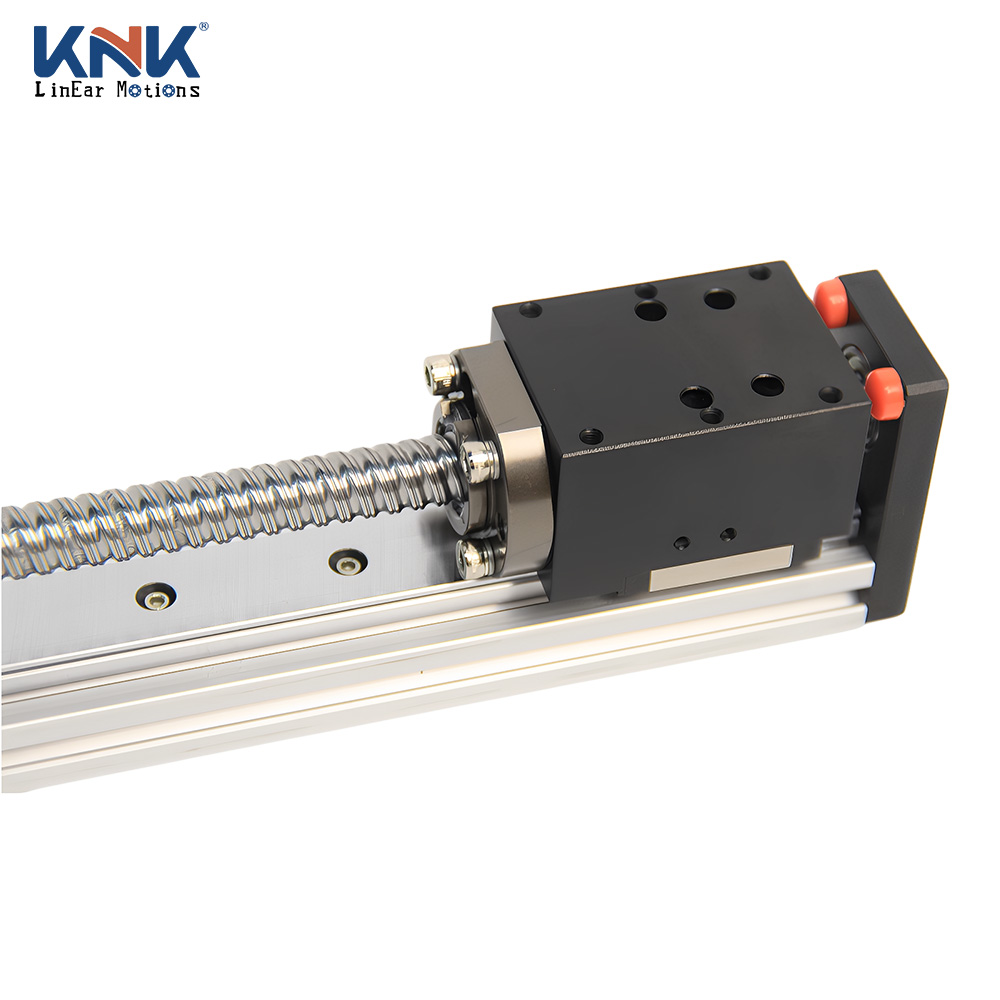
Three numbers define this module, and each one answers a different question in a buyer's evaluation.
| Max load | 150 kg |
|---|---|
| Max speed | 1000 mm/s |
| Position accuracy | 0.01 mm |
| Drive / actuator | Ballscrew series with embedded closed high-precision ball screw actuator |
Size the payload with the gripper, tooling and workpiece included, and treat the figure as the outer limit of the platform rather than a comfortable everyday working load. Vertical and cantilever layouts change how much of that figure is usable.
Ask for: the load case you intend to run, with orientation and duty cycle attached.
Top speed is only reachable when stroke, acceleration and the control profile allow it. Tell the supplier the speed you need over a defined move distance so the ramp can be checked against the drive you plan to use.
Ask for: the acceleration and settle profile at your working stroke.
It is the published accuracy figure for the module. Repeatability, backlash and resolution for your build are separate values — request them on the drawing rather than assuming they are covered by the same number.
Ask for: the accuracy budget split between module, mounting and measurement.
Four application patterns appear in the MR40G's published use context. Each one turns a different specification into the deciding factor of the quotation.
The axis repeats a short move many times a shift and the placement position has to hold.
Deciding fact: 0.01 mm position accuracy plus the closed ballscrew design that limits contamination from the assembly area.
Confirm before quoting: cycle rate, the accuracy you need at the tool, and the cleanliness of the cell.
Payload varies between empty and loaded, and the move profile is short and frequent.
Deciding fact: the 150 kg max load rating, measured with the gripper and the heaviest part included.
Confirm before quoting: gripper mass, offset from the carriage, and how much of the cycle is acceleration.
Throughput drives the decision and the environment usually carries dust or film debris.
Deciding fact: up to 1000 mm/s max speed, combined with a closed actuator that reduces maintenance exposure.
Confirm before quoting: required moves per minute over the real stroke, and the debris present around the rail.
Several axes are assembled into one structure, and each axis carries the axes mounted on it.
Deciding fact: compatibility with standard ball screw actuators, which supports use inside multi-axis systems.
Confirm before quoting: how many axes move on the MR40G axis, and the load each one adds.
Because most products are customized, the final quotation depends on the complete description, size, material and quantity supplied. A request that already contains these eight fields usually skips a round of questions.
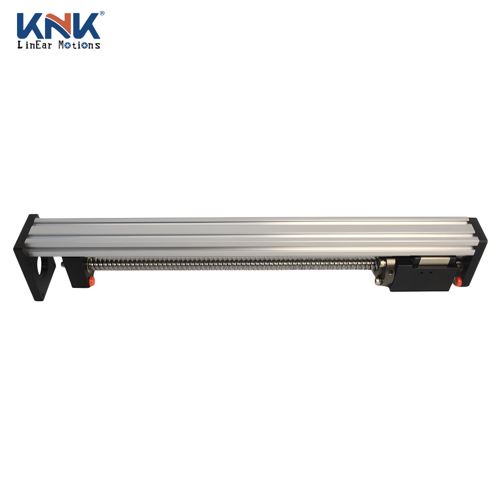
The module is only half the purchase. The other half is how the supplier handles a drawing, a change and a problem after delivery. KNK Technology (Dongguan) Co., Ltd. builds linear modules, linear rails and industrial manipulators, and customization on the MR40G is offered on a drawing basis for OEMs.
Load, speed, accuracy and drive type should be readable before you contact anyone — the MR40G page lists 150 kg, 1000 mm/s, 0.01 mm and a ballscrew drive.
Confirm the supplier will work from your drawing and return a confirmed plan before production starts, not after.
Ask what is checked on your build and what record comes with it; product testing sits inside the published process.
The MR40G product page offers a 3D image and a product manual download, which shortens integration work for your design team.
The published workflow ends with shipping acceptance, installation guidance and after-sales service — ask who owns each step.
Send the load, speed, stroke, accuracy target, mounting orientation, environment, motor preference and quantity. Pricing on the MR40G is quoted per build, so the completeness of that description is what sets both the price and the lead time.
Keep adjacent product options together for a faster catalog comparison.
0.05mm repeat positioning accuracy with 1000mm/s speed. The T Series integrates high-strength, modular design for reliable, cost-effective precision conveyor systems.
View product
Ensure stable automation with the KS series precision link conveyor. Featuring 1000mm/s speed and 40kg capacity, this robust conveyor link optimizes assembly.
View product
Eliminate downtime with the T Series Oval Belt Conveyor System offering 0.05mm repeat accuracy and modular design. Ideal for precision conveyor systems.
View productthe mr40g is rated for a maximum load of 150 kg, a maximum speed of 1000 mm/s, and a position accuracy of 0.01 mm. these are the published figures for the module, so any application requirement should be checked against them before the build is confirmed.
it is a ballscrew series linear module built around an embedded closed high-precision ball screw actuator. the closed ballscrew design limits external contamination and helps reduce maintenance requirements in demanding linear motion tasks.
yes. customization is available based on drawings, which supports oems that need tailored linear module specifications. because most products are customized, the final quotation depends on the complete description, size, material, and quantity of the product you need.
the module is described for automated assembly, component placement, pick-and-place equipment, robotics, automated feeding, packaging lines, cartesian robot frameworks, and xyz linear stage setups. its compatibility with standard ball screw actuators also supports use within multi-axis systems.
include the load with gripper, tooling, and workpiece; the speed you need over a defined move; the stroke; the accuracy target at the tool; mounting orientation; operating environment; motor and control preference; quantity; and whether a drawing or 3d model already exists. these details help the supplier confirm the most suitable configuration and quotation.
the published process begins with consulting customer service, then determining parameters, communicating quotations, confirming drawing plans, and confirming production. it continues through product testing, shipping acceptance, installation guidance, and after-sales service. a 3d image and product manual are also available on the product page to support integration.